Desk Lamp Reverse Engineering
-
![CAD to Object Comparison]()
CAD to Object Comparison
-
![Exploded Assembly Drawing]()
Exploded Assembly Drawing
-
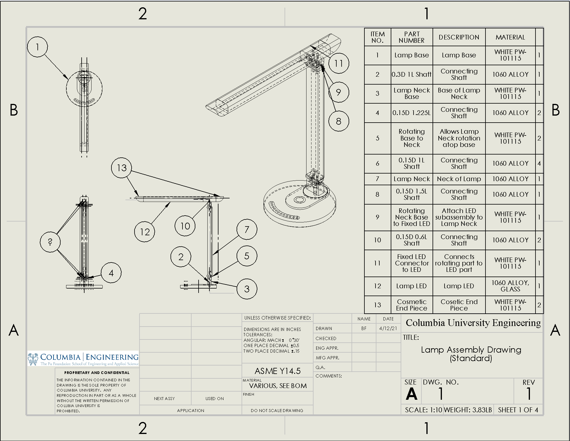
![Standard Assembly Drawing]()
Standard Assembly Drawing
-
![Lamp Base Drawing]()
Lamp Base Drawing
-
![Lamp Neck Drawing]()
Lamp Neck Drawing
-
![Base to Neck Connection Drawing]()
Base to Neck Connection Drawing


Project Summary
The objective of this assignment was to reverse engineer a household item of choice with at least five distinct parts. This item was then modeled in Solidworks, using as much realism as possible—including realistic dimensions and shapes.
Design Intent

When I began thinking of how to create my lamp in Solidworks, I first attempted to separate the overall body into distinct sections: the base, the neck, and the light. Each of these sections, however, could be broken down even further. For example, the base needed to incorporate the rotation angles of the real lamp, so there needed to be one part which lies on the ground, another part that rotates atop the first, and a part to connect those two parts. I tried to think about how I would build the lamp if I were tasked with manufacturing it from bottom to top, since that ordering made the most logical sense.
To make the base, I first extruded a circle upwards. I drew a slot atop, and extruded that farther upwards, then drawing a circle on the slot and extruding downwards to create a spot for the neck. I used the slot tool to create the light level slider, and a linear pattern along the axis of the curved slot to create the circles that appear in real life. The slot and the base circle were concentric. Finally, I added small details like the rubber grip on the wireless charger, the rubber on the bottom, and a chamfer on the bottom. Once I had built the base, the process of designing each subsequent part became much easier. As I made each part, I made sure to think about how the next part would connect with the one I was making, and how the next part would need to move relative to the one I was making. As I modeled, I made sure to put in holes for shafts that I would create later. After finishing all the parts, I went back and modeled the different shafts to connect them.
When mating the assembly, I wanted to make sure that the movement of the lamp was realistic as possible. I used an array of limit angle mates to constrain rotation of several parts to each other. This way, the base can stay still while the rest of the lamp moves from side to side. The neck can rotate from 0 to 180 degrees (or -90 to 90, depending on your POV) and tilt downwards up until the point that it collides with the base. Atop the neck, the LED parts can tilt forward and backward up until the point where they collide with the neck or base. Finally, the LED itself can rotate relative to the part is attached to from 0 to 180 degrees. Putting all of these limit angle mates paralleled the motion of the lamp in real life exactly.